
All UnetStack enabled modems have a Real-time Clock (RTC) to keep track of modem’s system time. A separate microsecond counter is provided by phy.time for Physical agent in UnetStack.
Although the clock (i.e., the hardware source of phy.time) is reasonably stable, it is impossible to guarantee that all the crystals of different computers will operate at exactly the same frequency. A crystal oscillator (XO) is an electronic circuit that uses the mechanical resonance of a vibrating piezoelectric crystal to create an electrical signal with the desired frequency. The resonant frequency depends on size, shape, elasticity, and the speed of sound in the material. Due to manufacturing tolerances, these properties are not identical across manufactured crystals, and so different crystals designed for the same nominal frequency produce slightly different frequency signals. Furthermore, as the operating temperature of the crystal changes, its material properties change, and so does its resonant frequency. These differences in frequency are tiny, but over long periods, the differences accumulate and cause the clocks to drift.
There are different oscillator types that exist to chose from including OCXOs, TCXOs, and XOs. The crystal controlled clock oscillator (XO) is a device that achieves its temperature stability from the quartz crystal’s inherent temperature stability. A temperature compensated crystal oscillator (TCXO) is a crystal oscillator with a temperature-sensitive reactance circuit in its oscillation loop to compensate the frequency-temperature characteristics inherent to the crystal unit. An OCXO is a crystal oscillator which is temperature controlled by a mini internal oven. This type of oscillator has a temperature controlling circuit to maintain a consistent temperature of the crystal and other key components. OCXOs are typically used when greater temperature stability is required. While this type of oscillator has a tenfold improvement over a TCXO for temperature vs. frequency stability, the OCXO tends to be higher in price and consumes more power.
NOTE: For example, UnetStack-based Subnero modems can be optionally upgraded to use low-drift clocks. Such clocks provide much better time stability and are suitable for such applications where time synchronization over long periods of time is critical.
Now, when there is a possibility of clock drift, it is not easy for having multiple spatially separated modems with synchronized physical clocks. So the question arises, if the synchronization of physical clocks across different UnetStack enabled modems is needed, how do we synchronize them with each other?
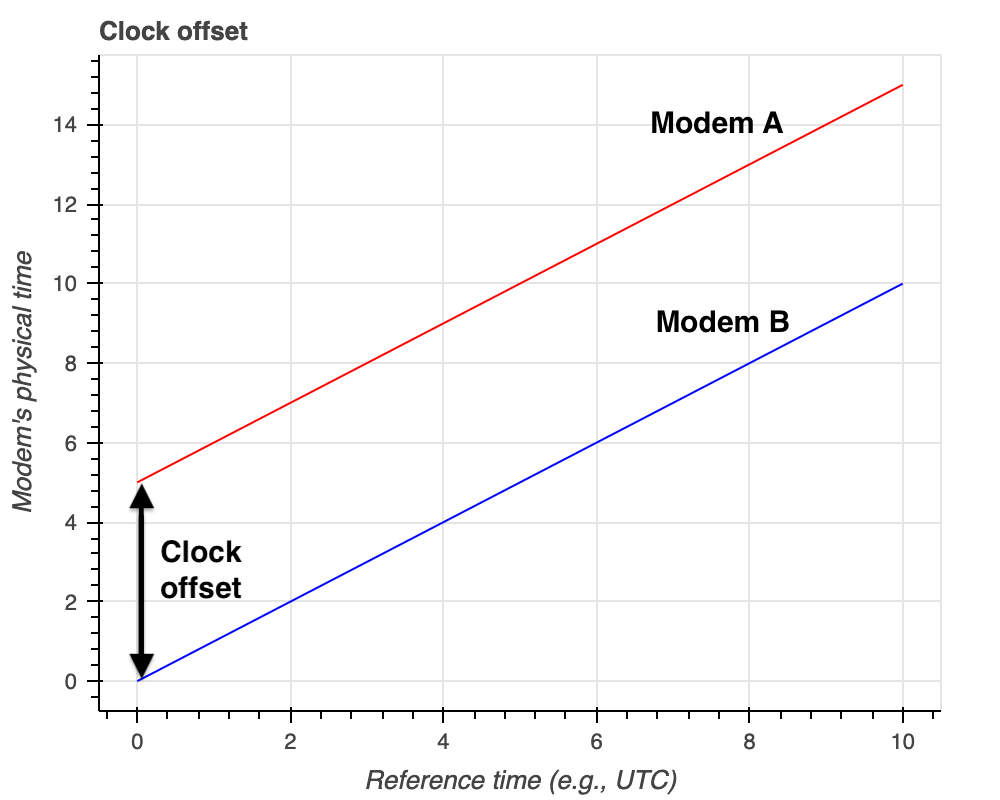
There are two major problems to be addressed to synchronize clocks among different modems:
- Modems start at different times so there may be a clock offset as shown in figure below:
- Modem clocks tick at different rates causing a clock drift as shown in figure below:
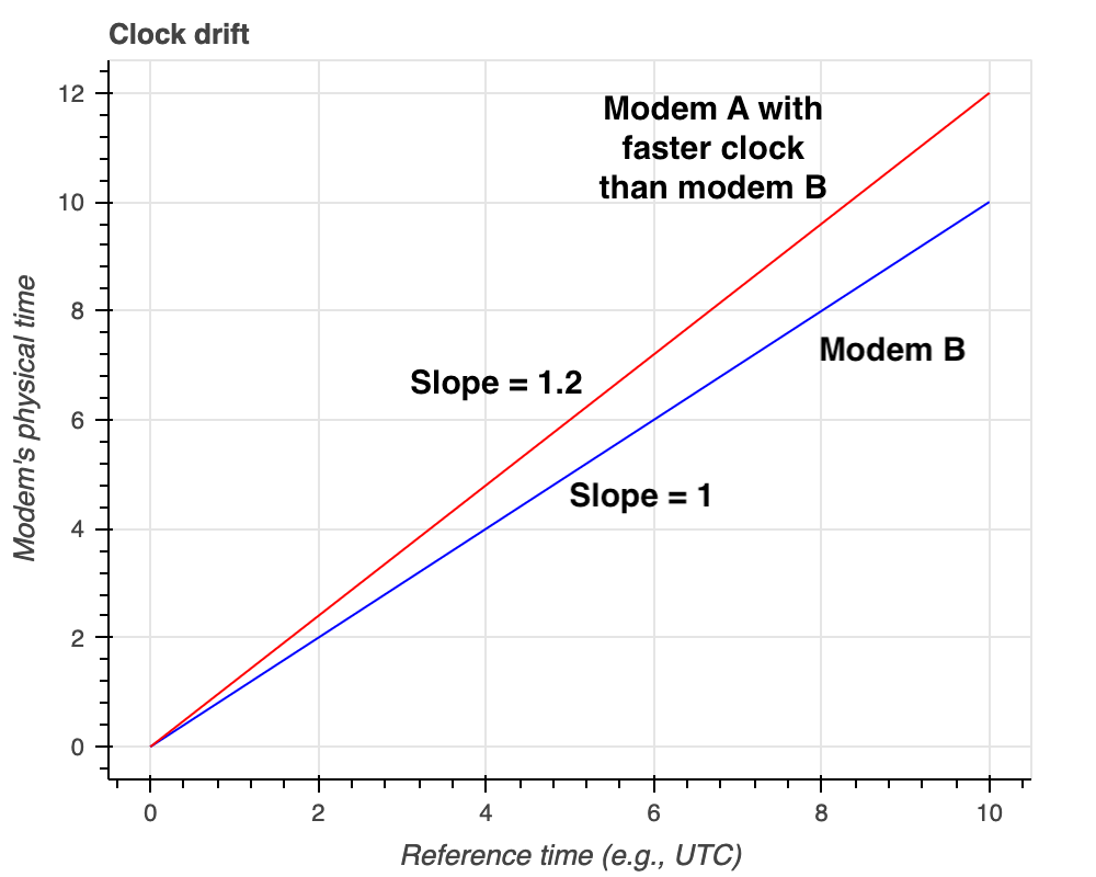
NOTE: The 20% clock drift shown in the figure is for illustration purpose only. In practice, the clock drift is expected to be much smaller in parts per million.
Compensating for clock offset
The Ranging agent in UnetStack running on the modem generates the clock offset information based on the message exchanges when range measurement is performed on the modem that initiates ranging. The clock offset between the two modems is populated in the ranging agent’s parameter ranging[host('B')].offset. Where host('B') is the node address of modem B. More details on this can be found here.
Once, the clock offset is known, it can be used to adjust the time locally to synchronize the physical time (phy.time). However, if a low-drift clock is not used, there is a possibility that the clocks tick at different rates, and clocks drift faster. Let us take a look at how we can compensate for the clock drift next.
Compensating for clock drift
Since the modems might tick at different rates, one modem’s clock may be faster than the other. An example is shown in the figure above where Modem A’s clock is faster than Modem B, i.e., a slope of 1.2 on Modem A’s clock. To compensate for this, the user of the modem can utilize a phy.clockCalib parameter. This parameter is a multiplier on the physical clock. So its default value is 1. If you set it to 1.2 the clock will run at 1.2x the rate of the actual hardware clock.
Therefore, to compensate Modem A’s clock to run slower so that it matches Modem B’s clock, we can set phy.clockCalib = 1/1.2 = 0.83.
The users of the modem should make measurements to figure out the nomimal values that they should set for phy.clockCalib.
An example of calibrating clock
We will consider two modems A and B for this example. To synchronize modem A’s clock with the modem B’s clock the following procedure may be followed:
- Make a measurement of system time and physical clock time on modem A.
To measure system time, open modem’s web shell and type the following:
1
2
> phy.rtc.getTime()
To measure physical clock time, open modem’s web shell and type the following:
1
2
> phy.time
phy.rtc.getTime() returns the number of milliseconds since January 1, 1970, 00:00:00 GMT represented by this Date object (phy.rtc). The phy.time returns time in microseconds. Make a record of both these measurements in the same unit.
-
Repeat Step 1 after 1 hour and make another measurement. This step should be repeated hourly until the desired number of hours.
-
Plot a graph with measurements of system time on x-axis and physical clock time on y-axis.
-
Fit a straight line among these measurements.
-
Compute the slope of the line, say
mA. -
Repeat Steps 1-5 on modem B.
-
Compute the slope of the line, say
mB. -
To match the clocks to tick at the same rate, set modem A’s clock calibration parameter to following:
1
2
phy.clockCalib = mB/mA
We show here a simple code snippet to run on two modems (say A & B) to measure the slope and compute the calibration factor to set phy.clockCalib parameter. The code presented makes measurements every hour and runs for 24 hours.
On modem A:
1
2
3
4
5
6
7
8
9
10
11
12
def interval = 3600*1000 // 1 hour in ms
def noOfMeasurments = 24
def phy = agent('phy')
def systime = []
def phytime = []
noOfMeasurments.times {
	systime.append(phy.rtc.getTime())
	phytime.append(phy.time/1000)
	delay(interval)
}
// compute slope based on measurements
mA = (phytime[noOfMeasurments-1] - phytime[0])/(systime[noOfMeasurments-1] - systime[0])
On modem B:
1
2
3
4
5
6
7
8
9
10
11
12
def interval = 3600*1000 // 1 hour in ms
def noOfMeasurments = 24
def phy = agent('phy')
def systime = []
def phytime = []
noOfMeasurments.times {
	systime.append(phy.rtc.getTime())
	phytime.append(phy.time/1000)
	delay(interval)
}
// compute slope based on measurements
mB = (phytime[noOfMeasurments-1] - phytime[0])/(systime[noOfMeasurments-1] - systime[0]) // slope
Now, based on the computed slopes (mA and mB), the modem A’s clock can be set to the following to match the clocks to tick at the same rate:
1
2
phy.clockCalib = mB/mA
NOTE: The RTCs are long-term synchronized through mechanism such as Network Time Protocol (NTP) and therefore provide stability for clock calibration.
Calibrating clock without relying on RTC
In the earlier section we relied on NTP to provide stability to the RTC clock which was used as a reference for clock calibration. However, in cases where there is no such means (e.g. NTP) to provide long-term synchronization for RTC, we can measure and compare the clocks of the two modems directly. In this section, we describe through a simple python script on how one can achieve this.
On user’s machine:
1
2
3
4
5
6
7
8
9
10
11
12
13
14
15
16
17
18
19
20
21
22
23
24
25
26
27
28
29
import time
from unetpy import *

# open a UnetSocket to modem A
modemA = UnetSocket("modemA-IP", 1100)

# open a UnetSocket to modem B
modemB = UnetSocket("modemB-IP", 1100)

# get physical agent ids on modem A and B
phyA = modemA.agent("phy")
phyB = modemB.agent("phy")

# measure phy.time on both modem A and modem B

interval = 3600 # 1 hour in seconds

noOfMeasurements = 24

phytimeA = []
phytimeB = []

for i in range(noOfMeasurements):
	phytimeA.append(phyA.time)
	phytimeB.append(phyB.time)
	time.sleep(interval)

# compute slope based on measurements
m = (phytimeB[noOfMeasurments-1] - phytimeB[0])/(phytimeA[noOfMeasurments-1] - phytimeA[0]) # slope
Now based on the computed slope (m), we can set either modem A or modem B’s clockCalib parameter to match the clock rate of the other modem. Therefore, we can either set phy.clockCalib = m on modem A (or) set phy.clockCalib = 1/m on modem B to match the clock rates.
NOTE: The parameters used in all the code snippets shown in this blog such as
intervalandnoOfMeasurementscan be varied as per the user’s need. The code snippets are to serve as reference only.